The Equalizer
With this work tool, we will be able to attenuate an annoying frequency, increase the bass range of a speaker, attenuate the so-called and feared “muddy area”, or to expand a bit the high notes on a voice.
The market offers a huge amount of both hardware and software models of equalizers, and none of them is the same.
I tend to think that it’s possible to do mainly two distinct jobs with equalizers; depending on the type, we can obtain extremely precise results, cleaning the sound and maintaining the overall timbre unaltered, or “coloured” results, used especially to enrich the sounds, giving them a more captivating flavour.
Because of these options, we have two different operational approaches, one aimed at correcting the sound, and the other at contextualizing it.
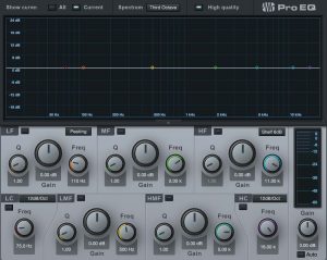
Fig1
With this work tool, we will be able to attenuate an annoying frequency, increase the bass range of a speaker, attenuate the so-called and feared “muddy area”, or to expand a bit the high notes on a voice.
The market offers a huge amount of both hardware and software models of equalizers, and none of them is the same.
I tend to think that it’s possible to do mainly two distinct jobs with equalizers; depending on the type, we can obtain extremely precise results, cleaning the sound and maintaining the overall timbre unaltered, or “coloured” results, used especially to enrich the sounds, giving them a more captivating flavour.
Because of these options, we have two different operational approaches, one aimed at correcting the sound, and the other at contextualizing it.
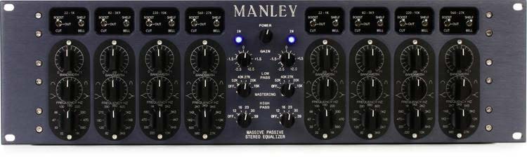
Fig2
As you can see from figures 1 and 2, the equalizer is made up of four filters (in some cases even more) that modify the tonal quality and frequency response of a sound.
To better understand its use, I will briefly describe the various sections.
- Low frequencies filter
- Medium-low filter
- Medium-high filter
- High frequencies filter
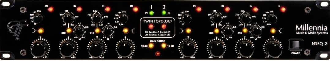
Fig3

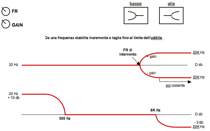
Shelving filters
Fig4
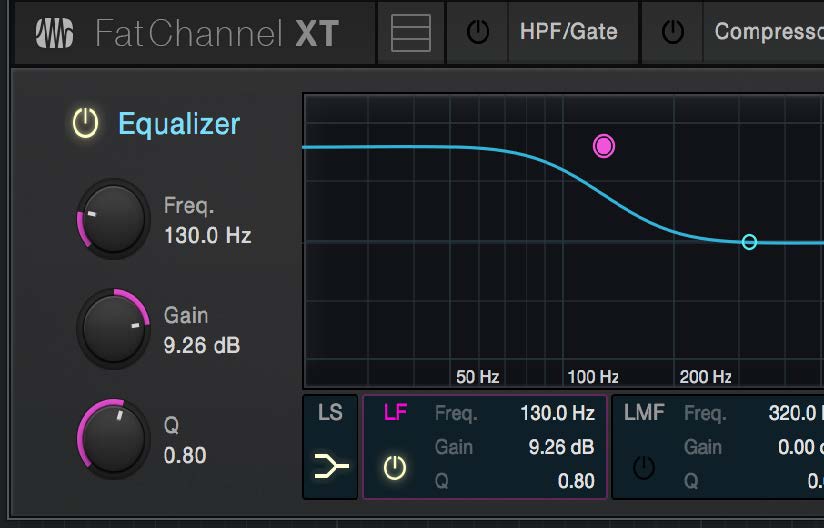
Shelf filter for low Fr, set to emphasize by 9 dB from 120 Hz down

Shelf filter for high Fr, set to attenuate by 9 dB from 5 kHz up
This type of filters is used to control the extremes on the audible frequency spectrum (see figure 4) and is equipped with 2 standard controls.
They are generally used to softly and transparently emphasize or attenuate low or high frequencies.
For example, if you want to make the overheads of a drum sharper, you can use a shelf filter for the highs, set around 8000 Hz, with a gain of a few dB.
The type of intervention will not distort the original timbre but at the same time will give a sharper appearance to the cymbals.
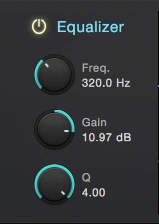
Main parameters
Let’s see the main parameters:
. Potentiometer for selecting the area of the frequency where you need to intervene (calculated at the point where the gain curve decays by 3dB in relation to the maximum value).
This parameter allows you to set a frequency value where you can decide to make the gain values (positive or negative) intervene from that frequency up to the audible limit of 20Hz or 20000Hz, depending on whether it is a Shelf for low or high frequencies.Gain: Applies an amplification or attenuation to the signal band above or below the frequency we’re intervening on.
Fig5
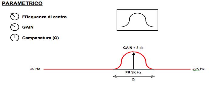
Parametric filters
Fig6

Wide Qcamber parametric filter (more frequencies involved)

Narrow Q filter (fewer frequencies involved)
This type of filter is used to control a limited portion of the spectrum and is equipped with three standard controls.
- Potentiometer to choose the center frequency. It’s the frequency at which the maximum (or minimum) gain on the curve occurs.
- Gain. It affects the amplitude of the frequencies involved within the curve, which can be both positive (amplification) or negative (attenuation).
- Quality factor (Q): It is a parameter that measures the ratio of center frequency to bandwidth, that is the width of the band of frequencies that are amplified (or attenuated). Relative bandwidth is measured 3dB below the peak.
Fig7
Thanks to this filter, we will be able to be very effective on our sound.
For example, if we want to attenuate an unwanted component, we will just have to search for the frequencies that make up this noise and then with a narrow curve and a negative gain, we will lower the sound without even affecting the rest of the timbre.
Hi-cut and Low-cut filters
These filters are the simplest in terms of construction and use. They are called subtractive filters because they can only attenuate the frequencies involved.
Fig8
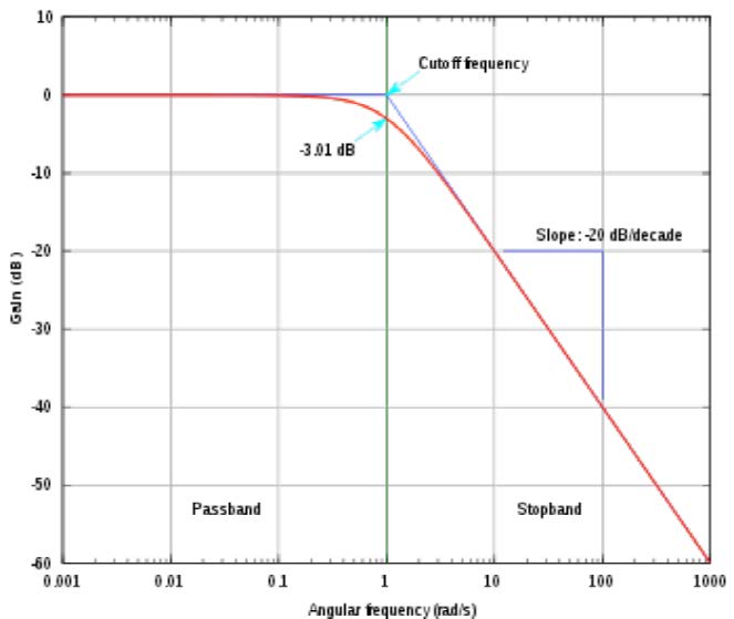
In Figure 8, you can see the graph of how a Low-cut filter behaves. The parameters on which you can act are the choice of the cut-off frequency and the slope. It should be noted that at the cut-off frequency, the filter will have already applied an attenuation of -3 dB, to partially compensate for the problems of harmonic distortion and induced phase rotation.
In the analog field, there are four orders of slopes:
- I ORDER – 6db / oct
- II ORDER – 12db/oct
- III ORDER – 18db/oct
- IV ORDER – 24db/oct
In Figure 8, you can see the graph of how a Low-cut filter behaves. The parameters on which you can act are the choice of the cut-off frequency and the slope. It should be noted that at the cut-off frequency, the filter will have already applied an attenuation of -3 dB, to partially compensate for the problems of harmonic distortion and induced phase rotation.
In digital, the slopes can be decidedly more incisive, even reaching values of -96dB per octave. In general, these filters are used at the extremes of the band to eliminate unwanted frequencies.
Well, that’s all for today!
Next time I’ll explain some tricks and methods to apply when equalizing a sound.
See you soon and good luck!
Simone Lampedone